Raspberry PI Pico based digital synth: Part 1
As established in the first post I’ve been always into electronic music (listening to Bassdrive pretty much all day long), but lately I’ve tried to combine it with my other interest: electronics. I decided I want to try to build a digital synthesizer. Analog seemed interesting as well, but since I’m a software engineer I probably will manage to get lot more out of a digital project.
TL;DR The project is here.
Components
What components does a digital synthesizer need?
- Something needs to run the software. For that we need a platform like Arduino or Raspberry PI
- If the platform doesn’t have an audio output we need to add it
That’s basically it for the mandatory components :) To make it more fun though you probably want the possibility to change a bunch of parameters of the synthesizer in some way and trigger the sound. You might also want to have a way to check out the current state of the synth somehow (a screen).
Extras:
- Digital inputs - buttons, rotary encoders
- Analog inputs - potentiometers
- MIDI input
- Screen
- Case
For the platform I decided to go with Raspberry PI Pico. Mostly because I already had one and I have no idea if an Arduino is powerful enough for what I’m trying to build.
To get the audio out of a Pico I got a Pico Audio Pack from Pimoroni. They also provide a useful Pico Audio Demo which is basically a synthesizer already.
The build
Pico only has three analog inputs I needed a 16-Channel Analog Multiplexer because I wanted to add more than three potentiometers.
Electronics
I built a prototype on a breadboard. That way I can quickly try things out and test the proof of concept by writing code before I commit to a proper build:
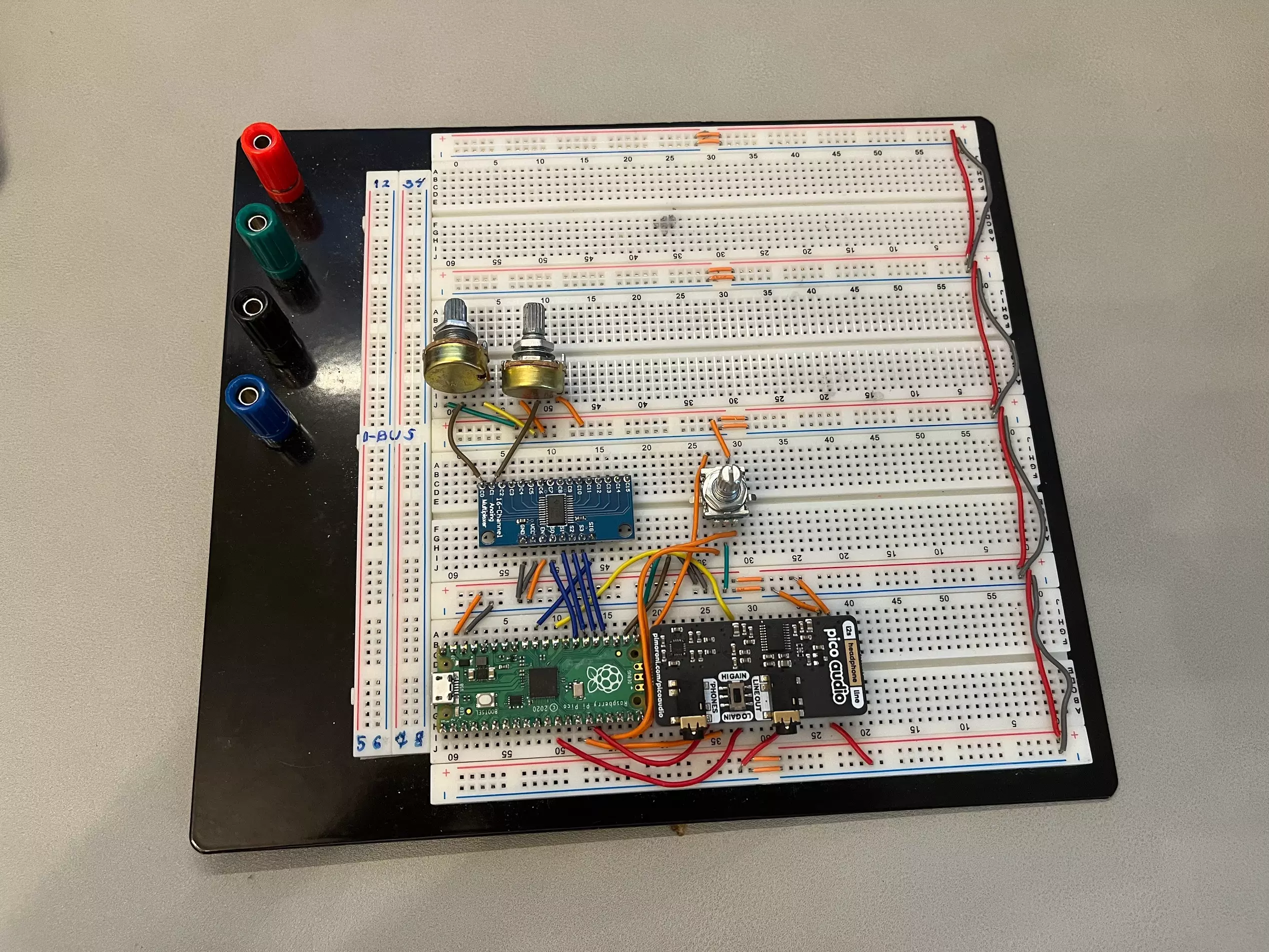
It’s just a Pico connected to the Audio Pack over I2C, a rotary encoder and an analog multiplexer (I already removed the screen, read on to know why).
I have already written most of the basic code to read the potentiometers, read rotary encoders, use the display, read switch states, trigger the synth with amp envelope. The code is here .
Case
When I had already planned what I wanted to add to the synth I decided to start prototyping the case. I have an Ender 5 Pro 3D printer, which mean I could easily throw together a few front panel only sketches in SketchUp, print them out and see what it would feel like.
First version of the faceplate: 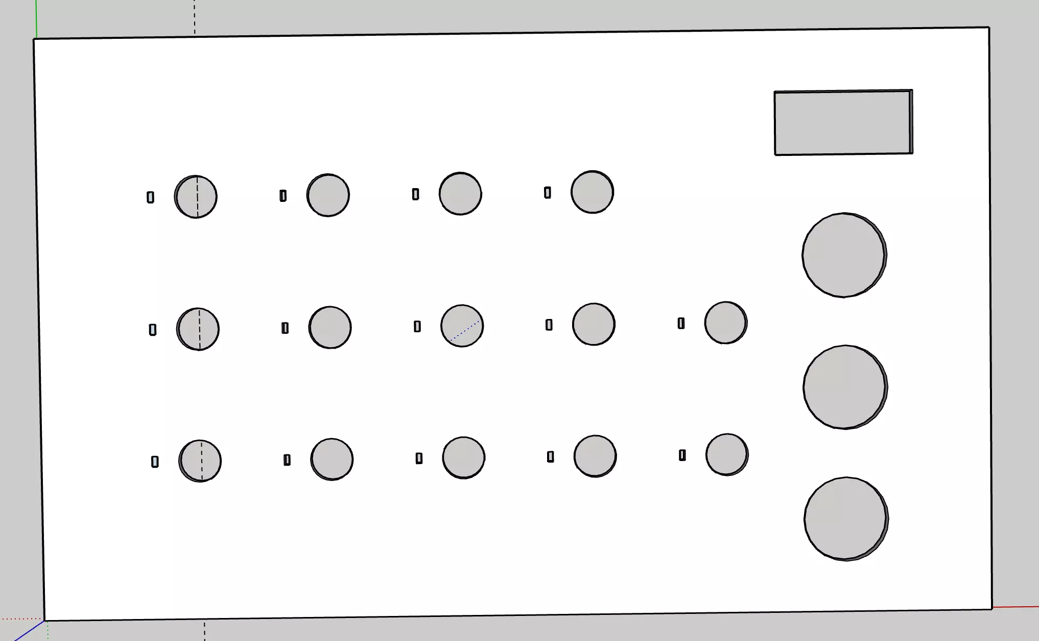
Leftmost column is for rotary encoders, rightmost column for push buttons, rectangle is for the screen and all the others are pots (small notches are to hold the pots in place). After printing it out I realised that the rotary encoder notches are on the top and not on the right, notches were too small and through the plate. I made the plate thicker, that way the notches can be hidden. I replaced one of the push buttons with a power button that is a bit larger.
Here is the second version: 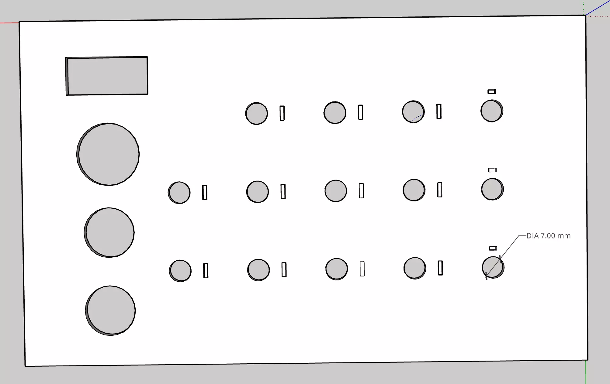
This was pretty good, but the plate thickness over the notches was not enough. You could see through it. I made the plate a bit thicker.
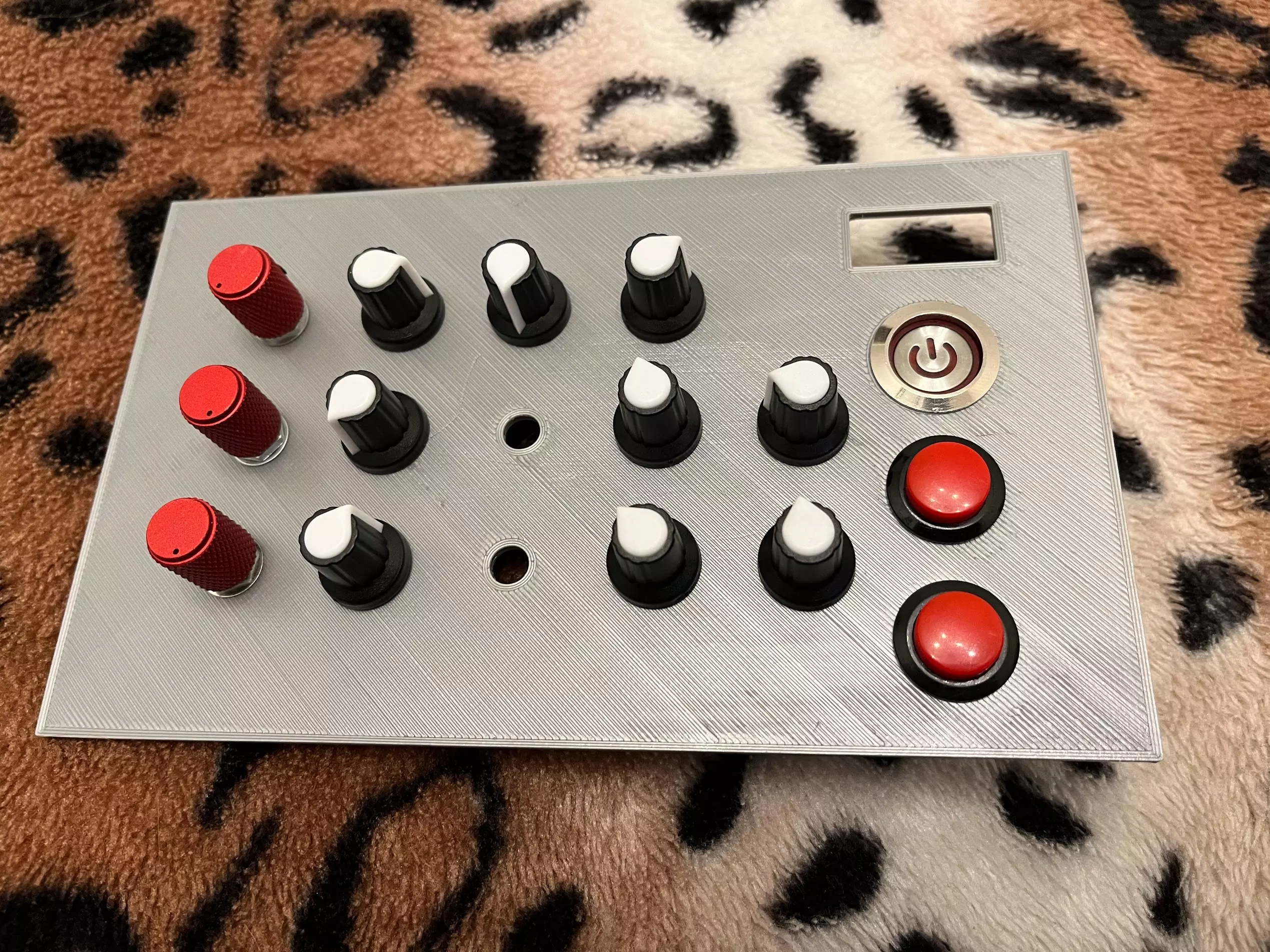
This is what it looked like with pots, encoders and buttons attached:
Conclusion
This is where I am currently, some things I’m rethinking:
- The screen is pretty small, 128x32 OLED. I’m replacing it with a 128x64
- I need more encoders and fewer pots. Pots have a fixed range and a specific value while encoders are endless and I can reset the values to whatever I want. Encoders do need a lot more pins though…
- Encoders have switches already built in, so I might remove one of the push buttons
Waiting for the screen to arrive, and then I will continue building and will post the second part of the project soon.